The smoke test. Am I still an engineer?
Am I still an engineer?#
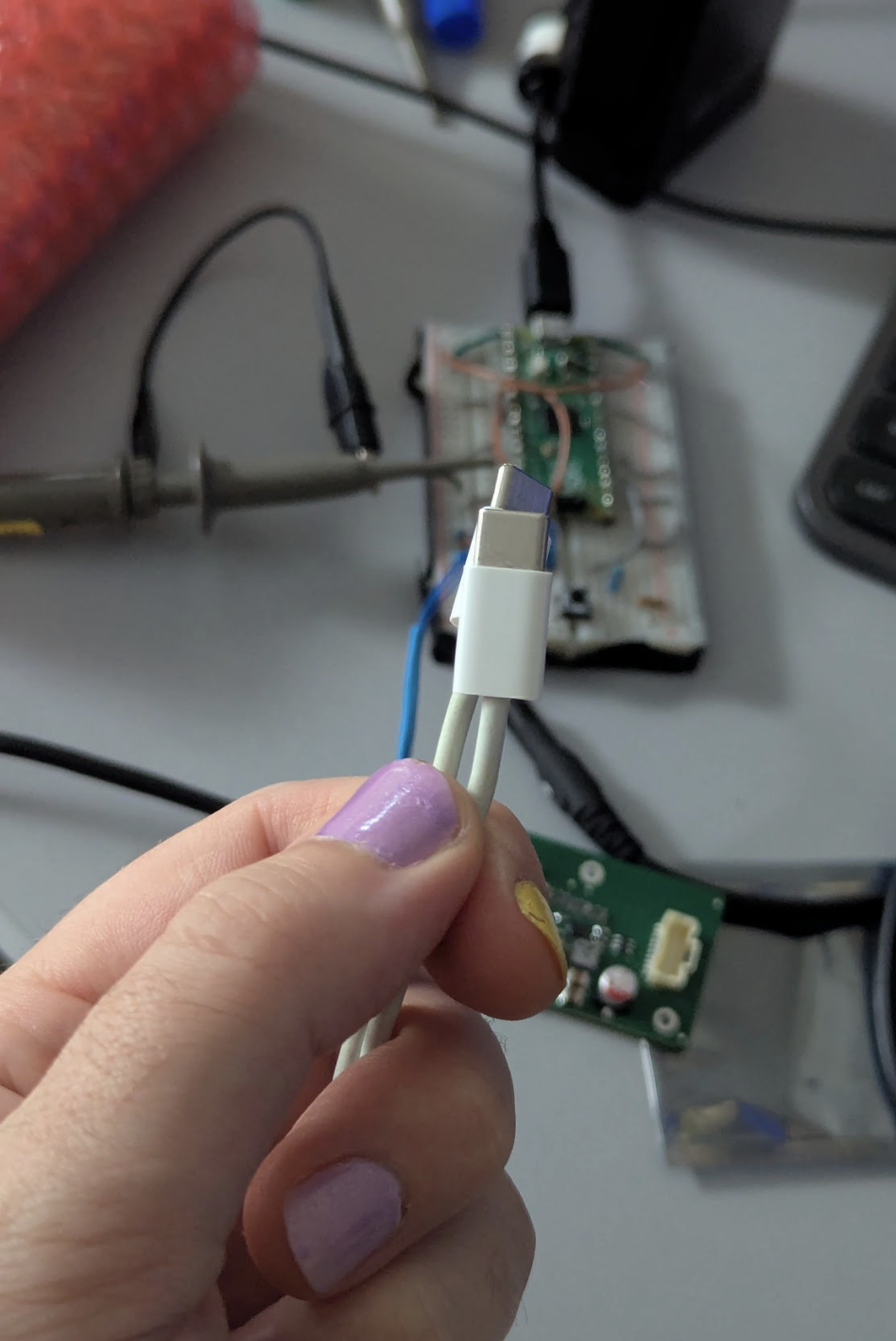
The question itself is pretty wild coming from me, someone working as an engineer, but hear me out. It’s been almost a year since I wrote any firmware or did any work on any microcontroller in general. This is then an excellent smoke test - do I still have what it takes? The premise is not too outlandish. Wire up an STUSB4500, tell it to negotiate 5V3A, 9V1.5A and 15V3A. A month ago, I placed an order with a Chinese manufacturer and received the boards last week. By default the IC does not negotiate 9V - which is incidentally the one I need, because that’s what the cheapest big capacity powerbank I chose to use does. For programming the device, I left a 100mil grid of testpoints that I intend to connect to using pogo pins. The 3x2 grid consists of 2 vias in opposing corners, a ground, a power and the I2C pins. Simple enough. An afternoon is all it should take.
When the I2C aint I-squared-seeing.#
What’s the big deal, right? I2C is dead simple, right? My big problem with this thing was the issue that I wrote my own i2c driver. Given that this is for a commercial venture, it made sense to - even if getting caught on a GPL piece of code is essentially non-existant here. The problem with rolling your own means that you add an extra layer of uncertainty. When you broadcast and the bus freezes, you expect it to be your shitty code. I was at work when I ran into this. I’m generally a printf debugger so my idea of solving this was sort of dead in the water. If you know that your circuit is good (it wasn’t) and that your device is alive, a printf is not going to tell you where you fucked up when the fuckup is between addressing the bus and broadcasting the message. You need a way to interrupt the code execution to do this. This is where you would normally use a debug probe. My problem though? My debug probe was the thing running the code. I’ve always had this issue - I flash a pico with the probe firmware, but eventually I need it to blink an LED or talk to some sand and I lose the probe. The idea to build a neon.Tap is already there in my head, but this will not help me now. Either way, I was still at work at this point, so the only real tool I had that would help me solve this was printf and hardware cues.
The first thing I figured out was that I fell for the oldest thing in the raspberry book. Pin numbers DO NOT MEAN GPIO NUMBERS. Pin 9 is gnd, pin 10 is whatever. I happily declared GPIO_SET_FUNCTION(9, I2C), or something like that.
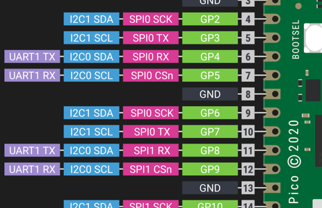
I wanted 6 and 7, not 9 and 10. This resolved the bus hanging on me. This is also, rule number 1 of debugging. Always question the bits you’re most certain of first.
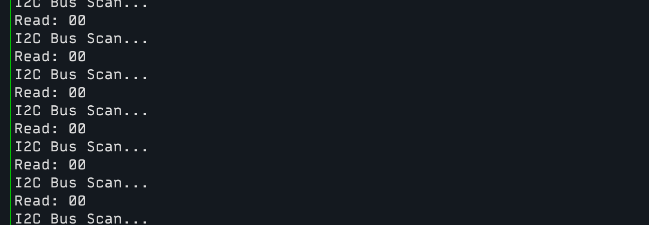
The next issue was to get the bus to respond with real data. The moment I got it to not freeze, I asked the chip some hard hitting questions. Who are you (print contents of 0x2f). Why are you here (please help I’m on a deadline). The chip replied with the iconic 0x00. For all registers.
I then tried simply to ask for acnowledgement from the bus. I broadcast on every address reasonable in this context. Told the firmware to print an ERROR for every address scanned that didn’t return anything. It printed an error for every address
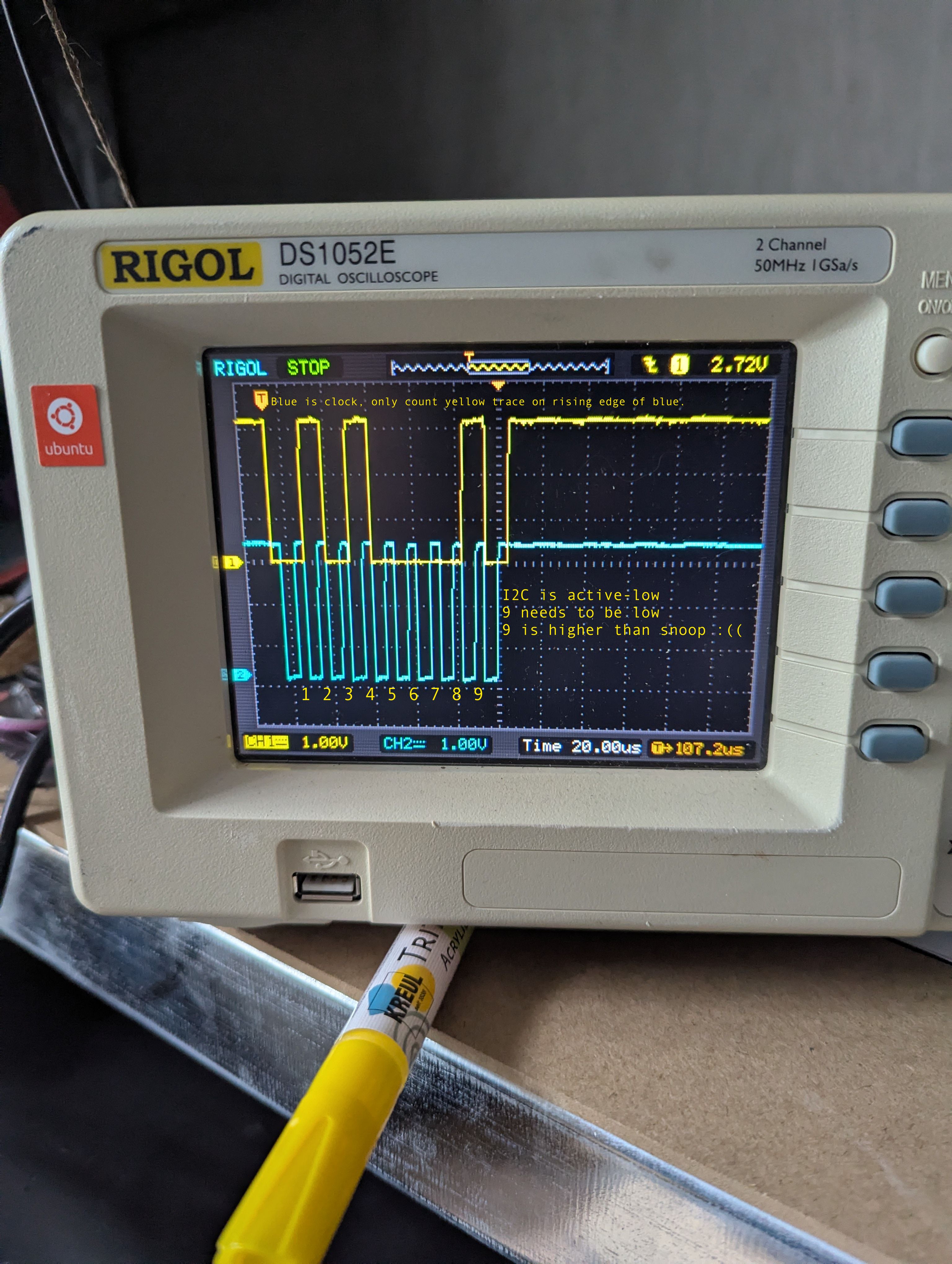
This is when I decided to do the smart thing and head home. I have my scope there. I don’t have one at work (yet). And it was the scope that told the truth. The ACK was a lie. It wasn’t there. To the uninitiated, let me explain. I2C is a clocked 8 bit bus. This means data on the bus has to fit in those 8 bits and when the transmission finishes, a device will write on the bus that it got the message. Bit 9 is thus the ACK or acknowledgement bit. In my case, the slave or the device being addressed pulls it low when it realizes that it’s being talked to. This signals the master to keep talking. And it will keep yapping until it’s done or the ACK no longer comes. There’s no checks to this - in this sense the bus is dumb as bricks. You just tell it an address, the device either says aight lets go (ack) or bruh (nack) and then you go until you’re done.
So what do you try? When you get to this point and read a byte on the bus followed by no ack despite your byte reading the correct address with the correct RW bit, it’s clearly not an issue with the master, the transmission is clearly there. Well, I was mad at raspberry, I was mad at my reading ability AND it was like 8PM on a Friday, so I did the smart thing and went out to get smashed instead. There was a huge crowd at my favorite bar and there was a rave party at an old prison, so that’s what ended up happening.
The next day I took a crack at the board with a raging hangover. I’m known to produce occasionally brilliant work when I’m in this state and thinking back on it now, I should have committed to writing or something, because the STUSB was scary, the board was not giving up the beans and one shot at it made my head hurt.
I did take a look eventually. First thing to check was the circuit itself. I had my pico blasting I2C as it should have been, so the fault is on the board.
This came with a minor issue. The circuit is dead simple. It’s a copy of the app note with marginal modifications. RULE NUMBER 1 OF DEBUGGING THOUGH, RIGHT?!
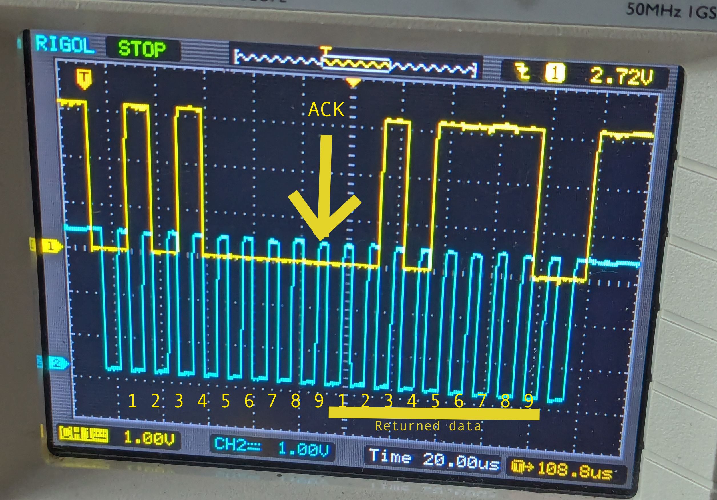
The modifications. How bad did I fuck up? I read somewhere in the datasheet (obviously not this datasheet), that the VSYS pin is meant to be used as a power backup for the system. This is what I intended to use to program I2C. Don’t plug in USB, just the pico via the pogo pins, blast 3V3 at VSYS like I’m a DJ at the rave party, go bbhleerrrghgh at the I2C and hope it understands. Well. I’m glad I didn’t connect to VSYS when I put 20V on VBUS (default PDO3 setting), because VSYS follows VDD. So I promptly desoldered that connection, bridged it to ground like the datasheet recommended to do, removed the I2C resistors, also removed the 100n cap from the pin and tried again. I vomitted a bitstream at the chip and… it did not terminate at bit 9. It gave me the ACK.
What. Seriously? FML.
I dropped the probe like I drop the bass and started dancing in my living room. It immediately reminded I had a massive headache and I dropped my whole setup - my ground clip is fucking sticky and it yanked the whole jank assembly to the floor. Alright though, it’s all good. This is what I was waiting for. This is what took a whole DAY to get to. It’s speaking I2C, finally. I carefully reassemble everything and probe it again to verify. No ACK. No biggie, I know I saw it just now, I’ll just double check the connections and try again. No ACK. It’s …dead? I plug it in, measure the board voltages. The STUSB4500 has 3 reference points, the internal 1V2 and 2V7 and the VBUS. Not present. None of them. No output.
Why? Something must have burned, right? Something must have shorted when it fell and now the thing is dead. No worries. I have 10 boards. I do the necessary mods to the next one, wire it up. Measure voltages - all good. Measure the bus - dead. Measure voltages - nothing. What gives. Okay, so what else can I do. What’s the best load test to a power module? Hook it up to something nasty. In my case, the something nasty was 2x 5 ohm resistors in parallel. The chonky 10W ones, and 4 5V fans in parallel in addition to that. Total load, around 2 amps. If the STUSB is alive and doing anything at all, the default 5V PDO is 3A - it’ll get me this power and it will get me this power with haste. I solder it up, my headache getting worse by the minute. I power it up. No voltage drop on the output. Rock solid. My thermal probe (pinky finger) says 5 seconds is the max it can touch it, meaning it’s between 50 and 60 degrees C. The fans though. They’re going, I leave them going for a while and then I notice that they’re not going. I replug the power bank. Starts up. I place the powerbank on the ground and the fans cut out.
The fucking type-c cable, “designed in California”.#
It’s now Sunday, I spent around 8 hours on this on Friday, around 3 on Saturday and today? It’s gonna start working today, no matter how long it takes.
I was a little bothered by this cable from the start. It’s the one I got with my iPad. It’s from 2018. It no longer has that that satisfying notch or click when it plugs in. It’s an Apple cable though, so surely it’s fine? Surely, Apple makes things that last.
It’s not. It really wasn’t fine.
The difference between good and bad contact with the powerbank is visually indistinguishable.
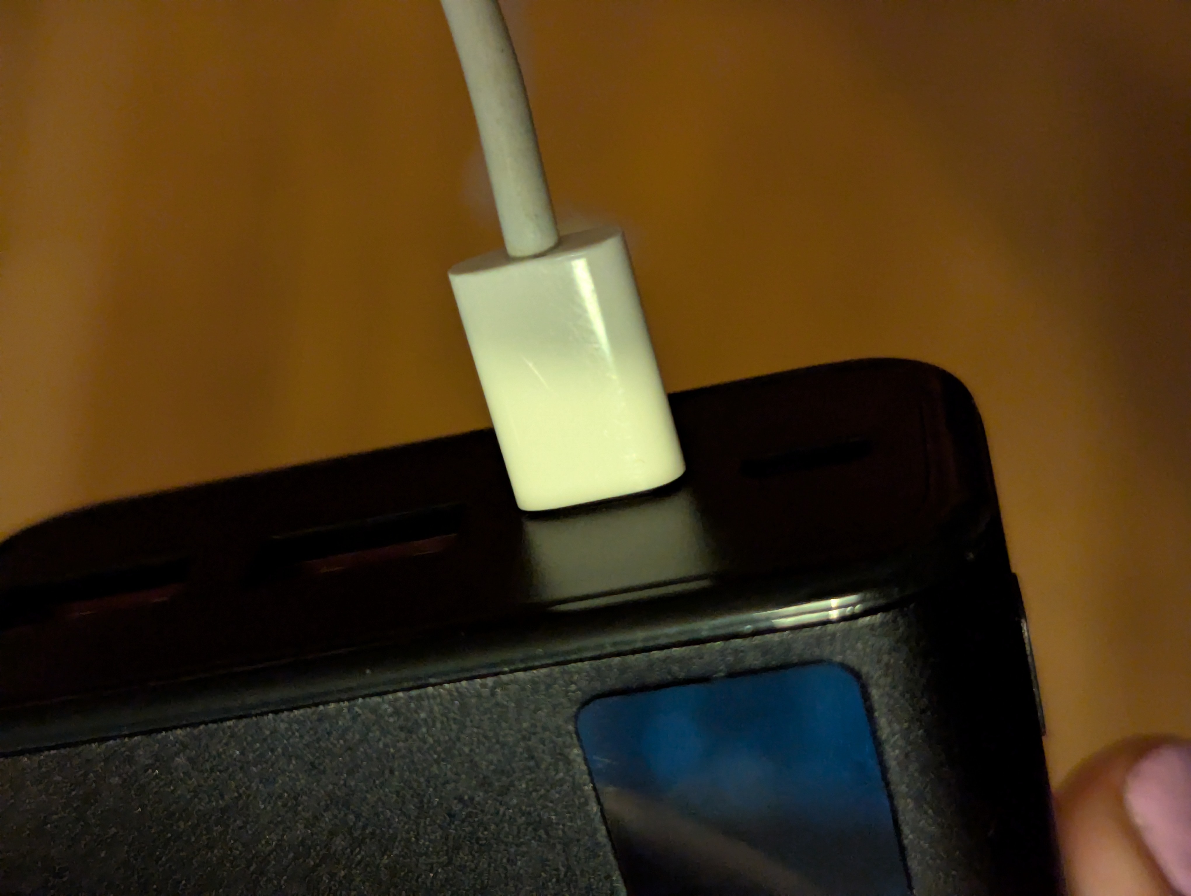
This is the cable properly plugged in.
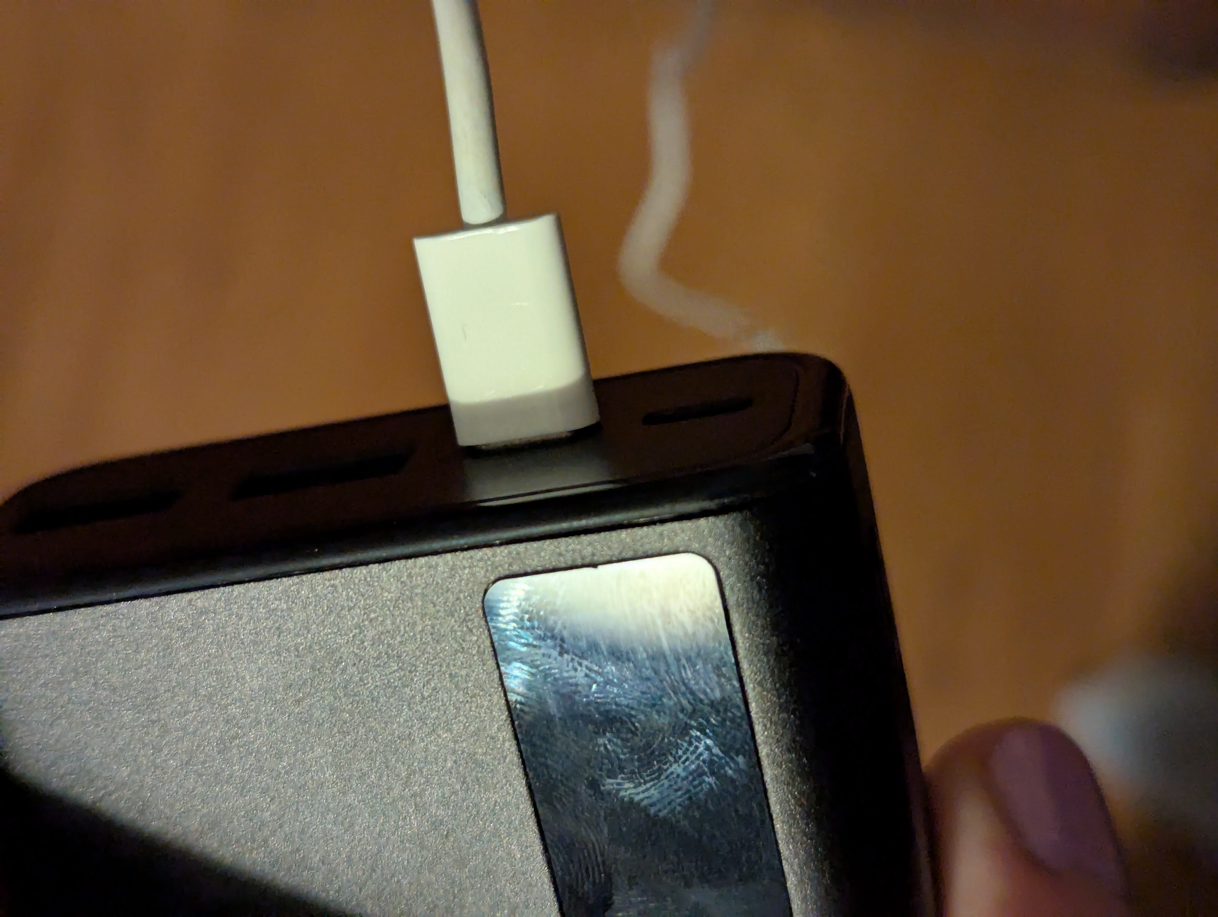
This is the cable disconnected.
Can you tell? I cannot.
I took a step back.
“There’s no way”
“How is this even possible?”
“Defeated by a cable”
It’s a fucking rite of passage. Every. Single. Time. You get beaten by something real dumb.
So anyway, since the chip is finally speaking my language, the rest is basically sorted (famous last words, It really wasn’t). I’ll leave the rest for tomorrow, the bitmaps for the registers are weird as the datasheet doesn’t exactly specify endianness, but it’s just a matter of time now.
I cracked open a cold one and I’m about to head out to my favorite bar, to wish one of the more fun bartenders around here good luck on his endeavors. It’s his last shift, he’s going to school next week. To become an electronics engineer.
volt.OS?#
This IC is gonna be running the USB show on the neon.Volt, so it’s getting this tag. Sure, this small power module is work-related, but this code is also going into my project. Well, parts of it at least. I’m not entirely certain I’m going to use most of its’ features though, but it’s good practice regardless. And despite all the moaning, I’m doing this because it’s genuinely fun. Frustrating, but fun.